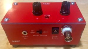
ZZRX-40 Completed and In the CaseThis little kit from the Four State QRP Group was a fun, easy build and, miracle of miracles for me, no magic smoke when I powered it on! I first heard about the kit during one of Erik Guth’s interviews on his QSOToday podcast (unfortunately, I don’t remember which one). That recalled an article I’d seen in July 2016 QST Magazine about this little regenerative receiver.
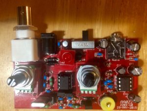
Completed Board Ready to Go Into the CaseI ordered the kit. The turnaround time was very fast, I was pretty busy, so it sat on the shelf for about a month. The instruction manual is very detailed with plenty of pictures. It’s pretty hard to go wrong with this kit!
However, mistakes happen. The kit has two potentiometers that need to be elevated above the board to go through the top of the case. The kit comes with a set of shims that are stacked one atop the other with four wires going through to the board and then soldered onto the board. It’s quite clever. I managed, however, to get one of the shims out of alignment which I discovered only after I’d soldered the stack to the board. Getting everything unsoldered and put back together correctly was a bit of a chore.
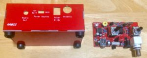
Board and Associated CaseThe receiver does work. I’ve ordered a VFO from eBay which is a week overdue for delivery. It’s coming from Turkey, where there have been a number of political / terrorism problems lately so I can understand that it’s taking more time to get here. I’m quite interested in seeing how the radio performs with a wide-range VFO. As currently configured, it is controlled by a crystal which can be pulled a few kHz above or below the crystal frequency.
K7AGE built this kit as well and put four YouTube videos up about his build experience. I watched his videos before starting my build and felt his experience was very helpful to me.
I’ll add more when the VFO arrives and I can try out that capability.
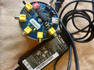
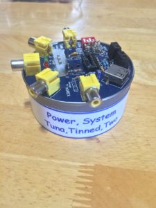
Tuna Power SystemThe second build of the Tuna Power System (TPS) is completed. Earlier I built one, tried to test it, but failed (see Letting Out the Magic Smoke). I took a lot more time and carefully built the second try. I was quite successful this time.
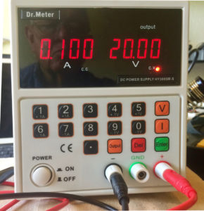
Dr. Meter Bench Power SupplyIn order to properly test the system, I needed a bench power supply. One that would allow me to set a specific voltage and a specific amperage, that would run with either constant voltage or constant amperage, that had short protection, and that I could afford. After listening to a HamRadio360 podcast having to do with workbench tools, I had an idea of what I wanted to buy. I found a Dr. Meter bench power supply on Amazon.com, ordered it, and really like the device. I definitely didn’t want to let out the magic smoke and ruin another device.
I first used the VOM to check continuity and resistance values at various places according to the circuit diagram. I got all of the expected readings. I then inserted the IC chip, connected up the Dr. Meter power supply setting the output voltage to 20 volts and the maximum amperage to 500 milliamps and turned on the Dr. Meter output. I was getting only about 5 volts into the TPS at a constant current setting. I upped the amperage to 1 amp and tried again. This time I got 20v input to the device, no smoke or shorts, and voila! 13.8 volts at the appropriate outputs and 5 volts ad the appropriate jacks. The IC stayed nice and cool.
Next step was to hook up the 20v wall wart power supply I picked up at a thrift store. This was a power supply for a printer and advertised 20v output at 4.5 amps. Again, the VOM read 20v input and 13.8 volts output at all the right places. And the IC stayed cool.
We’re ready to move onto the next two devices. I’ve got a Rexwood 1000 Receiver kit from QRPME.com. I’ve got that kit started and am ready to test the audio output section.
I also have a Pixie 40m Transceiver kit that I bought from Banggood.com for $3.82. This one comes with a PC board and components. No instructions or other information. There are some pretty good pictures on the Banggood.com site, so that will help with the build process. Capacitors are the most difficult for me to read, even with a 20x magnifying glass. To help with that I bought a capacitance / inductance meter also from Banggood.com. This wasn’t a kit, so I don’t have to put it to use before using it to figure out what the values are of each of the capacitors in the Pixie kit. I can read the resistors with my VOM.
Onto something that should receive RF and transmit as well as receive!
Tuna Power System Less the Magic SmokeAn effective QRP station needs a stable, regulated power source to provide power to the transmitter, the receiver (or a transceiver), an antenna tuner, as well as keep a battery topped off for use while off the power grid.
I felt like this would be a good first kit to solder together and ordered a Tuna Power System Kit from Rex (W1REX at QRPME.com). The kit arrived and the build instructions on the web looked very straight forward. However, the diode included with the kit would only work with small batteries. An option was to put in a diode with a higher power rating rather than the supplied 1N4004. So, I decided to order a small quantity of 1N4001 diodes. I found a set of ten diodes at Adafruit.com for $5.75 including shipping. Turn around on the order was very fast and I received the diodes three days later.
The instructions, as I said, seemed to be pretty straight forward, so I began building. It took me about four hours over two days to do the build, which included unsoldering several resistors and moving them to the right spot after making a pretty significant error.
I had a lot of problem reading the color codes on the resistors, even with the help of a 3x magnifying glass. Further, my inexpensive volt-ohm-meter (VOM) wasn’t accurate enough to figure out the exact resistance (even when shorted, the VOM would read a resistance of 2.5 ohms). There were some missing components and a couple of components in the kit that weren’t needed (several zero ohm resistors). Rex provides outstanding customer service and the situation was corrected literally over night.
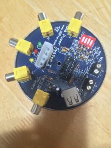
The power supply takes an input voltage from 15 to 20 volts DC and provides constant 12v out to five RCA jacks and to the battery connection. It also provides a 5v output to a USB connector and 5 volts and 12 volts to a molex connector. The suggested input device was a 20v power supply to an old printer. At the local thrift shop I found a 20v out power supply to an HP printer, cut off the plug at the end so that it would connect to the input jack.
Tuna Power System With the Smoke Let OutAfter soldering everything up, I did some testing with my VOM and felt I was ready to plug it in. Within seconds the IC chip caught fire between pins 13 and 14. Obviously, something was not right.
So, I’ve ordered another Tuna Power System Kit … plus several other items.
First, I ordered a 10x / 20x magnifying glass from Amazon. This glass has two LED lights which provide very nice illumination. The resistors are now much easier to read and it’s much easier to inspect the solder connections on the board.
Secondly, I needed a bench power supply … one where I could set the voltage and the current with shorts prevention. The problem with the first unit was probably a short circuit. A short circuit means that the device will pull as much current as the source will give, and in this case the 20v old printer supply would ship up to 20 amps on demand, more than enough to burn up the integrated circuit and surrounding components. A bench supply that would detect a short and shut down before something is damaged or catches fire was now a requirement for my kit building activities. After some research, I ordered one from Amazon.
Thirdly, I needed a much more accurate VOM that also included the ability to test and read capacitors. I ordered that from Amazon.
Finally, I needed a much finer point on the soldering iron to better prevent shorts between components. I found these also on Amazon.
All of that has arrived. The new power supply is now on the bench and ready for assembly. Nopefully no “magic smoke” this time.