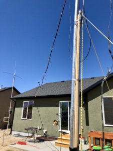
I tried 3/4″galvanized steel conduit and it wasn’t going to hold up. Far too much wiggle in the mast and it was impossible to get stood up without bending. So, I left the 10′ section of 3/4″ conduit as a kind of a gin-pole and went to 1-1/4″ galvanized steel conduit. The smaller size was rated for about 95 pounds while the larger size was rated for about 275 pounds. A significant difference for sure. So, yesterday afternoon everything was ready for the mast to be walked up into place.
A couple of fellows in the neighborhood volunteered to come over to help. It took about 10 minutes to put the mast into position, cinch it down, and hoist up the messenger line with the coax. That was enough for Tuesday evening. The finishing touches would wait until today (Wednesday, April 25th).
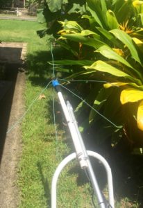
The Messenger Line and Coax to the House
The messenger line keeps the coax up in the air and above our heads. I did manage to guess correctly on how many carabiners were needed on the messenger line.
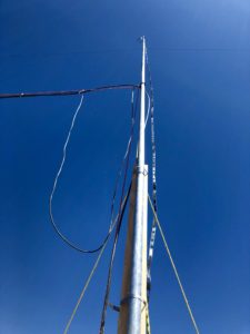
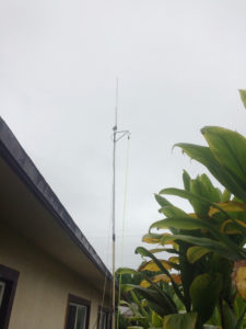
At the top of the mast I put a 2-meter J-pole antenna which will eventually be connected to an AllstarLink node. I just need to find my Raspberry Pi computers. There in a box somewhere!
Looking Up the Mast
This afternoon I completed the work to finalize the bracing for the mast and attached the LMR-400 coax to the window line coming down from the G5RV.
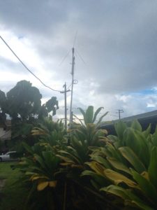
It’s in the later evening on the 25th now and I’m listening on the 40 meter band. That band is really booming tonight. I’m hearing signals from coast to coast as well as north and south. Just finished a QSO with Eric, KK6F in southern California. He was copying my 100 watt signal at a 57-58 whereas his amplified signal at 400 watts was booming into here. I think the antenna works. I sure is quiet compared to the G5RVJr up on my roof!
After letting the concrete harden over the weekend, Jimmy “The Handyman” came over on Monday. We pulled out the forms and filled in the hole. There was just enough dirt to be able to fill the hole, but I’m sure it’ll settle and compact. I really appreciated Jimmy’s help. I can get the rest of the project done now.
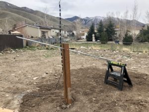
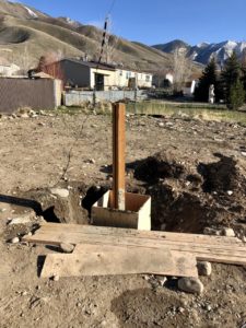
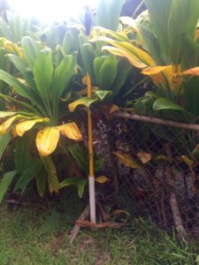
Yesterday I drilled a hole in the rigid conduit and the 4×4’s but ran out of time. This morning the next step came together. The holes lined up (!!) and the pivot point is in place.
So, the first ten feet of mast is ready. Twenty-five feet left to go!
The remaining steps?
Get three more lengths of rigid conduit from Home Depot, nineteen carabiners, and 100′ of paracord
Cut one of 10′ lengths of rigid conduit to a six-foot length (put the 4′ section aside for some possible future project)
Screw the two 10′ sections and the one 6′ section together with the section already installed. Make sure they’re tight
Install a hook about 12′ up for the messenger line coming from the house
Tie carabiners every foot and a half along the paracord messenger line. The two coax cables will ride along the messenger line in the carabiners. The messenger line length is 29 feet from the house to the mast
Install the pulley for the G5RV center and pull rope
Install the 2-meter J-pole
Measure (thrice), mark (twice) and cut the coax to length
Install connectors on both ends of the coax cables
Thread the coax cables through the carabiners
Connect the coax for the J-pole to the J-pole
Lift the mast upright and secure to the 4×4’s
Secure the bottom of the window-line for the G5RV antenna. The window-line needs to be at least six inches away from the conduit so they don’t interact
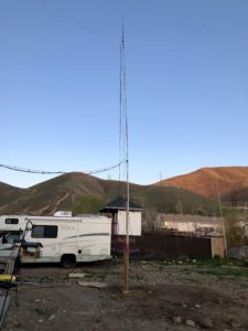
After almost three weeks of rain, snow, freezing temperatures, more rain, and more snow, a couple of days ago spring broke through. The ground has dried out, the snow on the local mountains has disappeared, and everything was ready to move to the next step with the antenna mast I’m putting up in the back yard.
I ran across a “handyman” by the name of Jimmy who was willing to come over and help me get the foundation dug and the cement poured. Yesterday I picked up 21 eighty-pound bags of Sakrete from Home Depot. reserved a cement mixer for today, and got all the tools in readiness. Jimmy arrived a little past noon and we got underway.
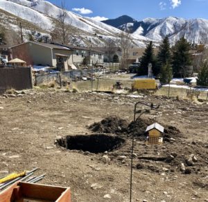
Hole Dug, Foundation Poured
When the hole was the right depth we built the cement forms to provide for two feet of concrete with the 4×4 posts in the center. Then we fired up the cement mixer and proceeded to mix twenty-one bags of concrete and pour that into the box.
Three hours later, 2,500 pounds of concrete were in the box ready to cure. I’m pretty sure the wind won’t blow this over!
Jimmy will come back on Monday when we’ll take the forms apart and fill up the hole.
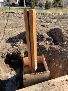
A Closer Look at the 4×4 Posts
Between the two posts is where the 3/4″ galvanized steel pipes will sit. Bolts through the posts and the pipe will secure the mast to the posts. The top bolt, which will be about six inches below the top will serve as a pivot point. Two more bolts will secure the pipe.
The concrete comes up to about three inches below ground level so it can be covered with dirt and grass planted around.
One last item to stick in before we fill in the hole is a copper grounding rod. The galvanized pipe will be secured with a copper strap to the grounding rod. We don’t get much lightning around here, but it’s still a very good practice to ground the pipe!
So, Monday the hole will get filled in and I can start on the mast. I won’t need Jimmy’s help with that.
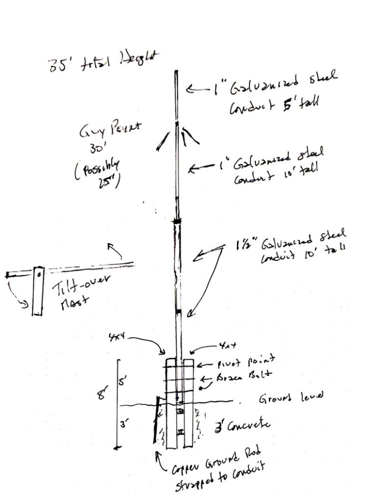
As described in an earlier post, the mast will be thirty-five feet high with a pulley afixed (about six inches from the pipe) to haul up (or down) the G5RV antenna. The window line will come straight down and mounted (with a six-inch standoff) to the 4×4 posts. I’m also going to put a two-meter J-pole antenna at the top of the mast and use that for an AllstarLink node I want to put up here in Tooele. So I’ll be running two coax cables out to the mast. One will be LMR-400 which will connect to the G5RV and the other RG-213 that’ll connect to the J-pole. I’ll run a messenger line from the edge of my roof out (about twenty feet off the ground) to the mast with carabiners every foot or so and the coax will ride in the carabiners. The coax then goes down a pipe up on the roof that I had installed when we built the house and into my shack.
When this is finished in the next couple of weeks, I’ll have the full-sized G5RV running roughly north-north-west to south-south-east diagonally across the back yard. The 2-meter J-pole will be atop the center mast holding up the G5RV.
Across the peak of the roof is a G5RVjr which barely fits on the roof. To the side of the house up about 20 feet are some military poles on which a 2-meter/70cm J-pole is mounted along with a twenty-meter ham-stick dipole. That antenna is oriented north and south to fill in the gap from the G5RVjr across the roof of the house, running east and west.
That will be 5 antennas. Enough for now. I’ll have coverage on 80-meters through 70cm across these antennas. Should be enough for a while.
When I first designed the mast to hold up the ham radio antenna, I felt that three feet below the ground encased in concrete would be sufficient. The engineer, however, came back and said the hole should be four feet deep with 24″ of concrete around the 4×4’s four feet deep (or just about one yard of concrete).
Several weeks ago the contractor who built my house had a track hoe working on a house down the street and he obligingly (and at no cost!!) dug me a three foot by three foot by three foot hole. I was amazed at the number and size of rocks that came up out of that hole. We have very rocky soil here in Tooele, thanks to ancient Lake Bonneville.
This morning I started digging and prying to get another foot or so down. After two hours, I think I’ve gotten four or five inches down. And this 73.9534 year old man is wiped out (another birthday Real Soon Now).
So, I called a handyman listed in the newspaper classifieds (remember those?). He can’t come over until Saturday, but thought he might be able to find someone who could come over on Wednesday. I think I’ll have him help with the whole project including mixing and pouring the concrete and backfilling the hole. Supervisor sounds much better than worker at this point!
The engineering firm completed their work last Thursday. The changes they asked for were minor. They felt that a 24″ diameter footing four feet deep would be better than a three-foot deep foundation. That means 4′ below ground and 4′ above ground, moving the pivot point down one foot.
Everything else was just fine. “The bolts and anchoring posts are sufficient to resist lateral loads at the base.”
So this morning I picked up the starting materials, the 4×4 pressure treated 8′ posts, the first length of galvanized steel conduit, and a bag of Sacreet cement. I’ll get the 4×4’s spaced properly, drill the pivot bolt hole in the 4×4’s near the top, and mix up some concrete. I’ll stand the 4×4’s in a Home Depot Homer’s Bucket and fill that with concrete. That’ll set in the garage for a couple of days before being moved to the hole in the backyard.
The hole is currently three feet deep. I’ll have to climb down there and dig out another foot. I’ll do that while the concrete is setting in the bucket in the garage. That’s going to be a Very Heavy Bucket!!!
The Hole for the Antenna Mast
I still need to stop by Tooele City Planning and get their final approval. I talked with the guy on the phone and read him what the engineer said. He grunted, then said I could proceed but to stop by his office to drop off a copy of the engineering. I’ll do that on Monday.
It’s going to take a week or so, but the mast is coming. I’ve decided to put a 2-meter J-pole antenna at the top of the mast to use for a Allstar node. I’ve got the radio, the Raspberry Pi, and interface unit. It just needed an antenna.
Of course, an antenna needs coax. I had my trusty Xfinity installer guy (lives up the street) come over and climb up on the roof. I have a hundred feet of LMR-400 coax, so he fed that down to me along with a length of Radio Shack RG-58U coax (very lossy coax, but should be sufficient for what I need for an Allstar simplex node). The LMR-400 will connect to the G5RV antenna and the RG-58U will connect to the home-made 2-meter J-pole.
Now that we’re in our new house in Tooele, Utah, getting the radios up and operational are a bit of a priority, obviously behind getting moved in and settled, but pretty high.
One of the criteria for where we were going to build the house was to free of an Home Owners Association or any other CC&R’s. That was successful. So, the first antenna up was a hamstick dipole set for 20 meters. It’s up on military poles at the side of the house, with a 2meter / 70cm j-pole on top. The hamsticks were nicely resonant on 20 meters … until they were up at 20′. They are now resonant a fair bit above 20 meters. Dang.
I hired a local satellite dish installer to come over and put up a G5RV Jr. antenna across the peak of the roof. That antenna is almost directly east and west, meaning it’s lobes are north and south. When it is working, the antenna goes very nicely into Canada…. However, the ladder line comes down from the antenna and then down the roof. It worked pretty well until we got winter. There’s now a foot of snow on the roof burying the ladder line and the SWR is through the roof. As long as there’s snow, I’m back to using the non-resonant hamsticks. Not a great situation.
So, I decided to put up a full-sized G5RV antenna stretching from the peak of the house on the west side to the back of the yard on the southeast side. The antenna would barely fit and would line up approximately north-north west to south-south east. A good orientation. With that, I did a lot of research and designed a fold-over mast to put up in the middle of the back yard where the apex of the G5RV would be up at 35′, about as high as I could get it.
The Mast Design Sketch
So, the next step was to determine if there were any hoops at City Hall I needed go navigate. Unfortunately, there was. The city planner didn’t like my engineering. Even though it would never fall on any one else’s property and was not a fire hazard, he required “real engineering”. So, that’s what’s happening now. I’ve engaged an engineering firm. It’ll cost twice as much to get the engineering done as to actually build the mast.
And, of course, winter has finally arrived. The three-foot hole in the back yard is full of snow. I won’t be able to do anything before April. Dang again.
At our previous address I built a 40 meter dipole that worked somewhat well. I was able to make a few contacts even though the band conditions over the summer were very poor. At least the afternoon Hawaii net on 40 meters was workable. The antenna apex was about 25′ above the ground and the legs in a sloping inverted V configuration coming down to about 10′ above the ground. The antenna was oriented northwest to southeast which would put the major lobes towards North America and towards New Zealand and Australia. The SWR measured between 1.3:1 to 1.5:1 across the 40-meter band. It also had similar SWR on 15-meters.
Then came the requirement to move. I tried to put the same antenna up here. Because of limited places to guy the painter pole holding the apex of the antenna, I was only able to get it about 18′ above the ground. The legs were again in an inverted V configuration, but also angled away from the antenna. Rather than having a 180° spread, the angle was closer to 150° on one side and 210° on the other. The antenna also was in an east/west orientation, meaning the main lobes (what there was of them) went north and south. Further, at that height, the takeoff angle was no lower than 60° making the antenna at best NVIS. The legs were attached to an 8′ 2×2 board velcro’d to the fence and had to go through quite dense foliage. I had 50′ of Radio Shack RG-8u coax to go from my Yeasu FT-897D to a 1:1 current balun at the apex of the antenna, meaning that about 30′ of coax was coiled on the floor behind the radio.
The SWR was horrible; resonance was 7.045 Mhz with an SWR of 7.3:1, too high for the built-in tuner to accommodate. I have an MFJ-971 portable tuner that I bought to use with my (still in the box, not yet powered up) Xiegu X1M Pro QRP transceiver. With that I was able to bring the SWR into a more reasonable range, but the SWR fluctuated across a very wide range from the wind in the foliage. Further, the coil of coax was also acting as an inductor with a lot of capacitance further screwing up the signal. I then picked up at 20′ piece of Radio Shack RG-8u coax, that improved the power output considerably, but the FT-897D did not like the SWR fluctuation at all. The antenna was simply non-functional. Down it came.
As an aside, we have an excellent Radio Shack about a half-hour away to the northwest in Hale’ewa. This is one of about ten still open stores in Oahu, but the only one that actually stocks parts. All the other stores are concentrating on selling cell phones and audio cables with literally no other stock. The store in Hale’ewa, however, keeps a fully stocked parts section. I love that store!
I have a Buddipole antenna system, the “long” version. It works very well, but takes me a half hour to get set up, guyed down, and tuned. It’s not at all advisable to leave this antenna up in the Hawaiian salt air / volcano ash / frequent rain showers weather. That was the reason for thinking about putting up a 40-meter dipole so when I had a few minutes I could sit down at the radio and see what was happening. As we move into “winter” (a strange term in Hawaii), band conditions will favor 40 and 80 meters.
I may still try to find a way to get a north/south orientation and trim that 40-meter dipole down into a 20-meter configuration. A 20-meter dipole is quite a bit shorter … we’ll see. We’re only here in Hawaii for 4 more months and then will be moving back stateside.
This antenna is a J-Pole antenna I purchased on the Internet in April, 2015 from Arrow Antennas after I arrived in Hawaii. I have a similar antenna in storage back on the mainland. I’ll leave this antenna here with someone who needs one when I leave in February, 2017.
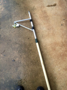
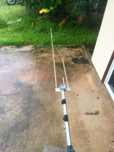
HF Dipole MountI decided to put this antenna on top of a 16′ painter pole I was going to use for my HF dipole antenna. The dipole mount wouldn’t be in the way of attaching the J-Pole above it.
J-Pole Attached to the Painter PoleThe aluminum bracket to to attach the J-Pole fit nicely onto the painter pole. However, the bolts supplied by the manufacturer weren’t threaded the entire length and I ran out of thread before the bracket could be firmly attached. Another (!) trip to Ace Hardware to buy two more fully threaded bolts ($1.07 including tax) solved that problem.
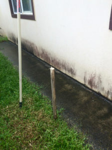
Support Post Pounded Into the GroundI wanted the installation to be removable when I leave next February with literally no trace left behind. I decided to put a post in the ground, a PVC pipe on the post, and then insert the pianter pole into the PVC pipe. I could then attach the pole to the roof at the 10′ level and use two guy ropes at the 16′ level to help stabilize the pole. I bought a four foot dowel 1 1/2″ in diameter, cut a point into one end, and then pounded it into the ground about 18 inches. That would provide the bottom support. The house has a small sidewalk that goes along the side of the house. The edge of the roof overhang is directly above the edge of the sidewalk. Consequently the antenna pole would go straight up past the roof where it could be attached.
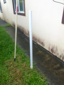
PVC Pipe SupportI next cut a four foot section of 1 3/4″ PVC pipe from Ace Hardware. That slipped over the dowel. The dowel stood about 2 1/2 feet above the ground. The painter pole would be inserted into the PVC pipe and rest on top of the dowel. The painter pole is about 1 5/8″ in diameter, a nice tight fit into the PVC pipe.
J-Pole Antenna ErectedThe painter pole is inserted into the PVC pipe, attached to the roof, and stands about 18′ tall. Two guy ropes go from the top down to the edge of the roof to provide additional stability (the picture was taken after the pole was secured to the roof.). The guy ropes are hanging down in the picture and were attached to the edge of the roof after the picture was taken. The ropes from the pulley are for the HF dipole antenna that will be put up next.
There are three repeaters in the area that can potentially be reached from my location. One is about a mile away at BYU-Hawaii campus. Another is thirteen miles west. That repeater is currently running low power because of a problem with the amplifier. When that gets fixed (it’s been down for several months) and I can finally hear it again, that repeater is linked into the state-wide emergency network of repeaters. Finally there’s another repeater nineteen miles south which I can now reach with this antenna.
Because of the move from Laie to Hau’ula a couple of weeks ago, I had to take down my antennas and put them back up again in the new location. The first antenna to go back up and into operation is a 2 meter ground plane antenna.
I took the original idea for the antenna from an article on hamuniverse.com. I bought some 14 gauge bar wire and some small bolts and nuts from Lowe’s along with 25′ of RG58 coax and an SO239 panel adaptor from Radio Shack. I built it as described in the link.
2 Meter Ground Plane Base
I threaded the coax up through a two foot section of 1″ PVC pipe from Ace Hardware. I used Gorilla Duct Tape (also from Ace) to hold the SO239 down on the top of the PVC pipe. Since the coax has PL259 connectors on either end, it mated up very nicely with the ground plane antenna.
The PVC pipe is attached to a 12′ painter pole that I bought at Lowe’s for this purpose. I drove a 1 3/4″ piece of PVC pipe (also from Ace) into the ground so that about 18″ were above the ground and stuck the bottom of the painter pole into the PVC pipe and the attached the pole to the fence. It has very low wind loading and has stood quite firm during the recent tropical storm that came through.
Erected 2 Meter Ground PlaneThis antenna is one of four antennas going up at my new address in Hau’ula. This antenna is connected to a Motorola 2 meter radio operating simplex on 147.450 Mhz attached to the AllStar network via a Raspberry Pi. See the AllStar category for information on that setup. The antenna has been an excellent performer. Together with the 20 watts output from the Motorola radio, I have excellent coverage throughout the Hau’ula and Laie area.