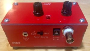
ZZRX-40 Completed and In the CaseThis little kit from the Four State QRP Group was a fun, easy build and, miracle of miracles for me, no magic smoke when I powered it on! I first heard about the kit during one of Erik Guth’s interviews on his QSOToday podcast (unfortunately, I don’t remember which one). That recalled an article I’d seen in July 2016 QST Magazine about this little regenerative receiver.
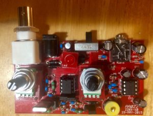
Completed Board Ready to Go Into the CaseI ordered the kit. The turnaround time was very fast, I was pretty busy, so it sat on the shelf for about a month. The instruction manual is very detailed with plenty of pictures. It’s pretty hard to go wrong with this kit!
However, mistakes happen. The kit has two potentiometers that need to be elevated above the board to go through the top of the case. The kit comes with a set of shims that are stacked one atop the other with four wires going through to the board and then soldered onto the board. It’s quite clever. I managed, however, to get one of the shims out of alignment which I discovered only after I’d soldered the stack to the board. Getting everything unsoldered and put back together correctly was a bit of a chore.
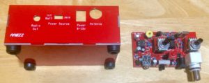
Board and Associated CaseThe receiver does work. I’ve ordered a VFO from eBay which is a week overdue for delivery. It’s coming from Turkey, where there have been a number of political / terrorism problems lately so I can understand that it’s taking more time to get here. I’m quite interested in seeing how the radio performs with a wide-range VFO. As currently configured, it is controlled by a crystal which can be pulled a few kHz above or below the crystal frequency.
K7AGE built this kit as well and put four YouTube videos up about his build experience. I watched his videos before starting my build and felt his experience was very helpful to me.
I’ll add more when the VFO arrives and I can try out that capability.
JT65 QSL CardsA couple of weeks ago the forecast was for several days of reasonably good weather for antennas. That is, lower winds, no rain or light rain showers, and lots of sunshine. I pulled out my Buddipole antenna and configured it for 40 meters at the low end of the band. After listening to some CW, I decided to set up JT65 and let it run for a while.
JT65 is a weak signal system. QSO’s are possible but take quite a bit of time to complete and even then, only a little bit of information can be transmitted. If the software is set up to send reports to pskreporter and to the Reverse Beacon Network (highly recommended to enable both options), every station that my software decodes will be reported along with the signal strength of the received signal. This is very helpful to others who are transmitting in the jT65 mode and want to know where their signal is being received and the relative signal strength of the received signal.
I let JT65 run for several hours while I was doing other things in the “shack”. I had a few minutes, so I responded to several CQ’s and managed to have two JT65 conversations. The first was with a ham in New Zealand and a while later I was able to make contact with a ham from Japan. I fired off a QSL card to each of them and included two one-dollar bills in the hopes they would send back a QSL card. Both did! The cards are in the picture above.
The weather here in Hawaii is not kind to things hanging out in the breeze. Consequently, leaving the Buddipole up for any period of time is asking for problems. In that period of time, one of the clamps on the tripod grew some serious crud that needed to be cleaned off and re-oiled. Now I’m hoping for another few days when the antenna can go up and I can try some more JT65. For more information on this app, please see JT65-HF.COM as well as the Wikipedia page on the mode / protocol.
The Robert E. Heytow Memorial Radio Club publishes a “general interest amateur radio eZine” called the “K9YA Telegraph“. I ran across it a little over two years ago, subscribed, and have enjoyed every issue since then, as well as have read several previous issues from the archive.
This is a subscription electronic magazine. The subscription is free. The current issue had some very interesting follow-on information about the National Air Race in 1929 and amateur radio involvement along with links to documentaries on the air race. The magazine comes as a downloadable PDF and usually is eight pages long.
The magazine has been serializing a story about amateur radio operators called “Rose”. Part fifteen was included in the latest issue. It is a well-written, quite engaging story and I usually read the next installment as soon as the magazine is downloadable.
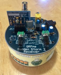
Rexwood 1000 ReceiverThe Rexwood 1000 QRP receiver was a straight-forward build. Two testing stages were part of the build. I had the first two stages completed several weeks ago, but needed the Tuna Power System (TPS) to provide power. I put the receiver aside and completed the TPS (see QRP Power Supply Completed and Tested).
I finished the rest of the receiver this afternoon. It is putting out sound. I need to put up some kind of an antenna to see if I can hear anything in the narrow range the receiver can tune: 7.030 and 7.0475 mHz +- a few kHz.
I’ve hooked the TPS up to the receiver and both seem to be working as advertised. Next I’ll start on the Pixie transceiver so perhaps it can provide a signal that the receiver can pick up to verify that it’s actually receiving something.
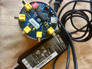
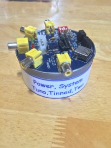
Tuna Power SystemThe second build of the Tuna Power System (TPS) is completed. Earlier I built one, tried to test it, but failed (see Letting Out the Magic Smoke). I took a lot more time and carefully built the second try. I was quite successful this time.
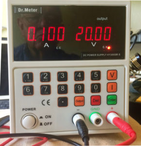
Dr. Meter Bench Power SupplyIn order to properly test the system, I needed a bench power supply. One that would allow me to set a specific voltage and a specific amperage, that would run with either constant voltage or constant amperage, that had short protection, and that I could afford. After listening to a HamRadio360 podcast having to do with workbench tools, I had an idea of what I wanted to buy. I found a Dr. Meter bench power supply on Amazon.com, ordered it, and really like the device. I definitely didn’t want to let out the magic smoke and ruin another device.
I first used the VOM to check continuity and resistance values at various places according to the circuit diagram. I got all of the expected readings. I then inserted the IC chip, connected up the Dr. Meter power supply setting the output voltage to 20 volts and the maximum amperage to 500 milliamps and turned on the Dr. Meter output. I was getting only about 5 volts into the TPS at a constant current setting. I upped the amperage to 1 amp and tried again. This time I got 20v input to the device, no smoke or shorts, and voila! 13.8 volts at the appropriate outputs and 5 volts ad the appropriate jacks. The IC stayed nice and cool.
Next step was to hook up the 20v wall wart power supply I picked up at a thrift store. This was a power supply for a printer and advertised 20v output at 4.5 amps. Again, the VOM read 20v input and 13.8 volts output at all the right places. And the IC stayed cool.
We’re ready to move onto the next two devices. I’ve got a Rexwood 1000 Receiver kit from QRPME.com. I’ve got that kit started and am ready to test the audio output section.
I also have a Pixie 40m Transceiver kit that I bought from Banggood.com for $3.82. This one comes with a PC board and components. No instructions or other information. There are some pretty good pictures on the Banggood.com site, so that will help with the build process. Capacitors are the most difficult for me to read, even with a 20x magnifying glass. To help with that I bought a capacitance / inductance meter also from Banggood.com. This wasn’t a kit, so I don’t have to put it to use before using it to figure out what the values are of each of the capacitors in the Pixie kit. I can read the resistors with my VOM.
Onto something that should receive RF and transmit as well as receive!
At our previous address I built a 40 meter dipole that worked somewhat well. I was able to make a few contacts even though the band conditions over the summer were very poor. At least the afternoon Hawaii net on 40 meters was workable. The antenna apex was about 25′ above the ground and the legs in a sloping inverted V configuration coming down to about 10′ above the ground. The antenna was oriented northwest to southeast which would put the major lobes towards North America and towards New Zealand and Australia. The SWR measured between 1.3:1 to 1.5:1 across the 40-meter band. It also had similar SWR on 15-meters.
Then came the requirement to move. I tried to put the same antenna up here. Because of limited places to guy the painter pole holding the apex of the antenna, I was only able to get it about 18′ above the ground. The legs were again in an inverted V configuration, but also angled away from the antenna. Rather than having a 180° spread, the angle was closer to 150° on one side and 210° on the other. The antenna also was in an east/west orientation, meaning the main lobes (what there was of them) went north and south. Further, at that height, the takeoff angle was no lower than 60° making the antenna at best NVIS. The legs were attached to an 8′ 2×2 board velcro’d to the fence and had to go through quite dense foliage. I had 50′ of Radio Shack RG-8u coax to go from my Yeasu FT-897D to a 1:1 current balun at the apex of the antenna, meaning that about 30′ of coax was coiled on the floor behind the radio.
The SWR was horrible; resonance was 7.045 Mhz with an SWR of 7.3:1, too high for the built-in tuner to accommodate. I have an MFJ-971 portable tuner that I bought to use with my (still in the box, not yet powered up) Xiegu X1M Pro QRP transceiver. With that I was able to bring the SWR into a more reasonable range, but the SWR fluctuated across a very wide range from the wind in the foliage. Further, the coil of coax was also acting as an inductor with a lot of capacitance further screwing up the signal. I then picked up at 20′ piece of Radio Shack RG-8u coax, that improved the power output considerably, but the FT-897D did not like the SWR fluctuation at all. The antenna was simply non-functional. Down it came.
As an aside, we have an excellent Radio Shack about a half-hour away to the northwest in Hale’ewa. This is one of about ten still open stores in Oahu, but the only one that actually stocks parts. All the other stores are concentrating on selling cell phones and audio cables with literally no other stock. The store in Hale’ewa, however, keeps a fully stocked parts section. I love that store!
I have a Buddipole antenna system, the “long” version. It works very well, but takes me a half hour to get set up, guyed down, and tuned. It’s not at all advisable to leave this antenna up in the Hawaiian salt air / volcano ash / frequent rain showers weather. That was the reason for thinking about putting up a 40-meter dipole so when I had a few minutes I could sit down at the radio and see what was happening. As we move into “winter” (a strange term in Hawaii), band conditions will favor 40 and 80 meters.
I may still try to find a way to get a north/south orientation and trim that 40-meter dipole down into a 20-meter configuration. A 20-meter dipole is quite a bit shorter … we’ll see. We’re only here in Hawaii for 4 more months and then will be moving back stateside.
Tuna Power System Less the Magic SmokeAn effective QRP station needs a stable, regulated power source to provide power to the transmitter, the receiver (or a transceiver), an antenna tuner, as well as keep a battery topped off for use while off the power grid.
I felt like this would be a good first kit to solder together and ordered a Tuna Power System Kit from Rex (W1REX at QRPME.com). The kit arrived and the build instructions on the web looked very straight forward. However, the diode included with the kit would only work with small batteries. An option was to put in a diode with a higher power rating rather than the supplied 1N4004. So, I decided to order a small quantity of 1N4001 diodes. I found a set of ten diodes at Adafruit.com for $5.75 including shipping. Turn around on the order was very fast and I received the diodes three days later.
The instructions, as I said, seemed to be pretty straight forward, so I began building. It took me about four hours over two days to do the build, which included unsoldering several resistors and moving them to the right spot after making a pretty significant error.
I had a lot of problem reading the color codes on the resistors, even with the help of a 3x magnifying glass. Further, my inexpensive volt-ohm-meter (VOM) wasn’t accurate enough to figure out the exact resistance (even when shorted, the VOM would read a resistance of 2.5 ohms). There were some missing components and a couple of components in the kit that weren’t needed (several zero ohm resistors). Rex provides outstanding customer service and the situation was corrected literally over night.
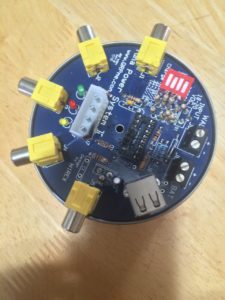
The power supply takes an input voltage from 15 to 20 volts DC and provides constant 12v out to five RCA jacks and to the battery connection. It also provides a 5v output to a USB connector and 5 volts and 12 volts to a molex connector. The suggested input device was a 20v power supply to an old printer. At the local thrift shop I found a 20v out power supply to an HP printer, cut off the plug at the end so that it would connect to the input jack.
Tuna Power System With the Smoke Let OutAfter soldering everything up, I did some testing with my VOM and felt I was ready to plug it in. Within seconds the IC chip caught fire between pins 13 and 14. Obviously, something was not right.
So, I’ve ordered another Tuna Power System Kit … plus several other items.
First, I ordered a 10x / 20x magnifying glass from Amazon. This glass has two LED lights which provide very nice illumination. The resistors are now much easier to read and it’s much easier to inspect the solder connections on the board.
Secondly, I needed a bench power supply … one where I could set the voltage and the current with shorts prevention. The problem with the first unit was probably a short circuit. A short circuit means that the device will pull as much current as the source will give, and in this case the 20v old printer supply would ship up to 20 amps on demand, more than enough to burn up the integrated circuit and surrounding components. A bench supply that would detect a short and shut down before something is damaged or catches fire was now a requirement for my kit building activities. After some research, I ordered one from Amazon.
Thirdly, I needed a much more accurate VOM that also included the ability to test and read capacitors. I ordered that from Amazon.
Finally, I needed a much finer point on the soldering iron to better prevent shorts between components. I found these also on Amazon.
All of that has arrived. The new power supply is now on the bench and ready for assembly. Nopefully no “magic smoke” this time.
Another of the ham radio operators here in the area is Paul Crookston, KB7ZIH. He’s been directly involved in getting the new BYU-Hawaii repeater up and operational. Tonight he worked with a group of boy scouts on their radio merit badge. He took his radio over and had the boys talk with several others of us who were standing by. A couple of the boys expressed some interest and hopefully there’ll be a way for them to act on that interest. The Boy Scouts of America operates an excellent website, K2BSA.net, and has been activating a number of locations using the K2BSA portable call sign. In October the scouts will be holding their Jamboree On The Air event. We’ll need to figure out how to get some of the local troops involved in JOTA.
So, now that the J-Pole is up and operational, my Yaesu FT-8900 easily gets into the BYU-H repeater. In fact, both of my HT’s easily get into the repeater at 5 watts output into a better-than-a-rubber-duck antenna. Monitoring the repeater this evening shows some activity on the machine. However, there’s a LOT of QRM here. I’m going to ask him to put a tone on the output side of the repeater which should go a long way towards squelching the QRM.
This antenna is a J-Pole antenna I purchased on the Internet in April, 2015 from Arrow Antennas after I arrived in Hawaii. I have a similar antenna in storage back on the mainland. I’ll leave this antenna here with someone who needs one when I leave in February, 2017.
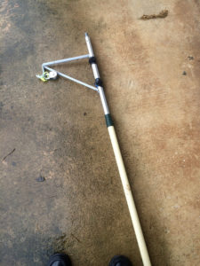
HF Dipole MountI decided to put this antenna on top of a 16′ painter pole I was going to use for my HF dipole antenna. The dipole mount wouldn’t be in the way of attaching the J-Pole above it.
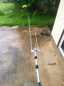
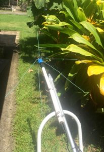
J-Pole Attached to the Painter PoleThe aluminum bracket to to attach the J-Pole fit nicely onto the painter pole. However, the bolts supplied by the manufacturer weren’t threaded the entire length and I ran out of thread before the bracket could be firmly attached. Another (!) trip to Ace Hardware to buy two more fully threaded bolts ($1.07 including tax) solved that problem.
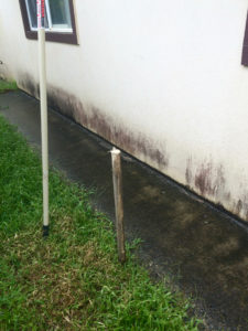
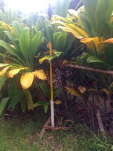
Support Post Pounded Into the GroundI wanted the installation to be removable when I leave next February with literally no trace left behind. I decided to put a post in the ground, a PVC pipe on the post, and then insert the pianter pole into the PVC pipe. I could then attach the pole to the roof at the 10′ level and use two guy ropes at the 16′ level to help stabilize the pole. I bought a four foot dowel 1 1/2″ in diameter, cut a point into one end, and then pounded it into the ground about 18 inches. That would provide the bottom support. The house has a small sidewalk that goes along the side of the house. The edge of the roof overhang is directly above the edge of the sidewalk. Consequently the antenna pole would go straight up past the roof where it could be attached.
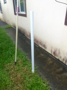
PVC Pipe SupportI next cut a four foot section of 1 3/4″ PVC pipe from Ace Hardware. That slipped over the dowel. The dowel stood about 2 1/2 feet above the ground. The painter pole would be inserted into the PVC pipe and rest on top of the dowel. The painter pole is about 1 5/8″ in diameter, a nice tight fit into the PVC pipe.
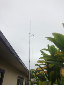
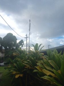
J-Pole Antenna ErectedThe painter pole is inserted into the PVC pipe, attached to the roof, and stands about 18′ tall. Two guy ropes go from the top down to the edge of the roof to provide additional stability (the picture was taken after the pole was secured to the roof.). The guy ropes are hanging down in the picture and were attached to the edge of the roof after the picture was taken. The ropes from the pulley are for the HF dipole antenna that will be put up next.
There are three repeaters in the area that can potentially be reached from my location. One is about a mile away at BYU-Hawaii campus. Another is thirteen miles west. That repeater is currently running low power because of a problem with the amplifier. When that gets fixed (it’s been down for several months) and I can finally hear it again, that repeater is linked into the state-wide emergency network of repeaters. Finally there’s another repeater nineteen miles south which I can now reach with this antenna.
Because of the move from Laie to Hau’ula a couple of weeks ago, I had to take down my antennas and put them back up again in the new location. The first antenna to go back up and into operation is a 2 meter ground plane antenna.
I took the original idea for the antenna from an article on hamuniverse.com. I bought some 14 gauge bar wire and some small bolts and nuts from Lowe’s along with 25′ of RG58 coax and an SO239 panel adaptor from Radio Shack. I built it as described in the link.
2 Meter Ground Plane Base
I threaded the coax up through a two foot section of 1″ PVC pipe from Ace Hardware. I used Gorilla Duct Tape (also from Ace) to hold the SO239 down on the top of the PVC pipe. Since the coax has PL259 connectors on either end, it mated up very nicely with the ground plane antenna.
The PVC pipe is attached to a 12′ painter pole that I bought at Lowe’s for this purpose. I drove a 1 3/4″ piece of PVC pipe (also from Ace) into the ground so that about 18″ were above the ground and stuck the bottom of the painter pole into the PVC pipe and the attached the pole to the fence. It has very low wind loading and has stood quite firm during the recent tropical storm that came through.
Erected 2 Meter Ground PlaneThis antenna is one of four antennas going up at my new address in Hau’ula. This antenna is connected to a Motorola 2 meter radio operating simplex on 147.450 Mhz attached to the AllStar network via a Raspberry Pi. See the AllStar category for information on that setup. The antenna has been an excellent performer. Together with the 20 watts output from the Motorola radio, I have excellent coverage throughout the Hau’ula and Laie area.